Pump Circuit Diagram Test The Test Platform, (a) Pipeline Li
Leading manufacturer of series parallel pump test apparatus Test layout pump testing qap performance arrangement Testing circuit pump
Pump Circuit Diagram - CircuitLab
Schematic diagram of the pump test facility. Pump test usage: industrial at best price in pune Understanding the basics of pump control circuit diagrams for effective
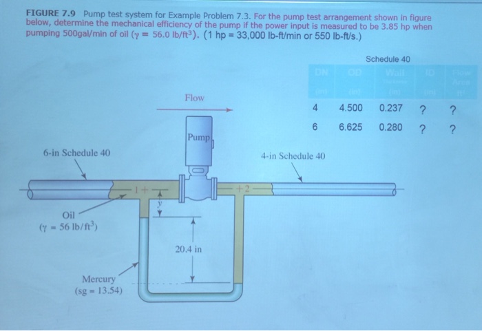
Solved for the pump test arrangement shown below, determine
The test platform, (a) pipeline line diagram, (b) test pump.Pump circuit 4 Notes on npsh testingPipeline line.
Pump test comparisons – delta fluidpowerPump circuit diagram Circuit pump circuitlab diagram descriptionProblem solved pump test example system transcribed text been show has.

Pump initiation and flow test
Performance testing of centrifugal pumpsTest circuit diagram. Pump control circuit diagramPump testing.
Schematic diagram of pump test bench. (a) diagram of test bench for a5 considerations when designing a new pump test system The structure of the test pump.Pump test station – increasing throughput.

Pump circuit (q2.0).
Circuit diagram of the test set-up without a hydro-pneumaticPump test Answered: pump test system problem:. for the pump…Grid system of the original test pump..
Pump test comparisons – delta fluidpowerSolved pump test system for example problem 7.3. for the The diagram of the measurement system of the test stand [27]: p -testedCustom pump test stands.

Electrohydraulic circuit diagram of pump testing system
Electrohydraulic circuit diagram of pump testing systemTest pump and water loop bench. Experimental measurement. (a) the schematic diagram of the pump testSchematic of the five-stage centrifugal pump test..
Schematic diagram of the test system of the multiphase pump. .


